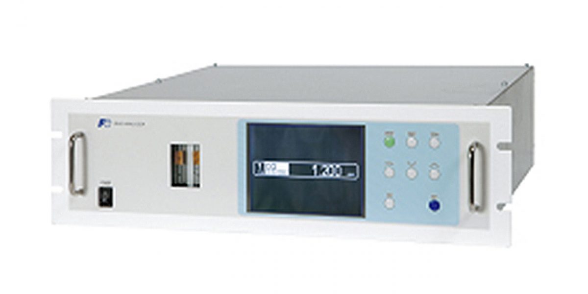
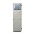
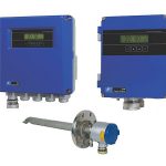
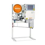
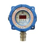
Continuous monitoring of low-level CO or CO2 in the air or the air separation facilities
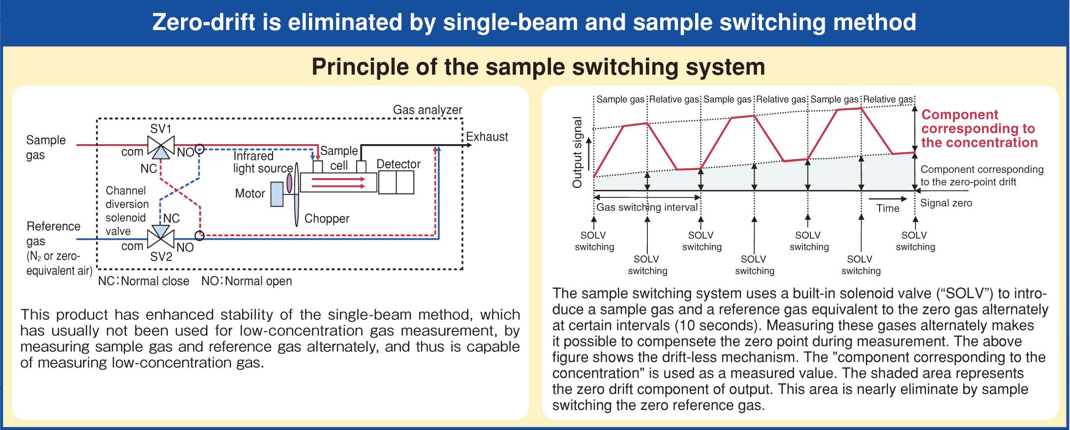
- Long-term superior stability: zero drift ±0.5% FS per week
- Compact and lightweight: 19-inch rack mount
- Continuous measurement of low concentration gas
- Built-in magnetic O2 sensor or optional galvanic O2 sensor
- Optional functions include: atmospheric pressure compensation, RS-485 communication, automatic calibration, alarm output, O2 correction, and more.
- Low maintenance
Specifications
| Principle | Non dispersive infrared sensor (single beam system) O2 sensor: built-in magnetic or galvanic sensor, or external zirconia sensor (ZFK7) |
|---|---|
| Measurable components and ranges | NO: 0–10 ppm…100 ppm SO2: 0–10 ppm…100 ppm CO2: 0–5 ppm…50 ppm CO: 0–5 ppm…50 ppm Built-in galvanic O2 sensor: 0–10 vol%…25 vol% Built-in magnetic O2 sensor: 0–5 vol%…100 vol% External zirconia O2 sensor: 0–5 vol%…25 vol% |
| No. of ranges | Up to 2 ranges per component |
| Repeatability | ≤ ±0.5% FS |
| Linearity | ≤ ±1% FS |
| Zero drift | ≤ ±0.5% FS per week |
| Span drift | ≤ ±2% FS per week |
| Response time (for 90%) | ≤ 30 s (Loss time may vary with gas switching timings) |
| Analog output signal | 4–20 mA DC or 0–1 V DC |
| Display | Backlit LCD (Japanese, English, or Chinese available) Instantaneous value, O2-corrected instantaneous value, O2 corrected average value, O2 average |
| Range switchover | by key operation, automatic, or by external contact input (option) |
| Contact input (option) | Voltage contact input (12–24 V DC, up to 15 mA) Remote range-switching, auto-calibration remote start, remote hold, average reset |
| Contact output (option) | SPDT relay contact (24 V DC/1 A) Device error, calibration error, range identification, auto-calibration status, solenoid valve drive for auto-calibration, limit alarm, CO peak alarm |
| Atmospheric pressure correction (optional) | Built-in option available |
| Standard functions | Output hold, auto/manual range switching |
| Option | Auto calibration, auto calibration remote start, remote hold of output, range identification contact output, high/low limit alarm, O2 correction, O2-corrected average values, average resetting contact input, CO peak alarm contact output |
| Communication (option) | RS-485 (Modbus) (9-pin D-sub output): half-duplex, start-stop synchronization system |
| Flowmeter | Provided |
| Gas inlet/outlet | Rc 1/4 or NPT 1/4 internal thread |
| Purge gas flow rate | 1 L/min (as needed) |
| Reference gas | Required (dry N2 or dry air) |
| Surrounding temperature/humidity | -5°C to +45°C, RH90% or lower (non condensing) |
| Power supply voltage | 100–240 V AC, 50/60 Hz |
| Power consumption | Approx. 100 VA |
| Dimensions | 133 (H) × 483 (W) × 382 (D) mm |
| Weight | Approx. 11 kg |
| Conformity | CE Marking |
Gas conditions
| Flow rate | 1.0 L/min ±0.2 L/min |
|---|---|
| Temperature | 0–50°C |
| Pressure | ≤ 10 kPa |
| Dust | ≤ 100 μg/Nm3 with particle size ≤ 0.3 μm |
| Mist | Unallowable |
| Moisture | Below the saturation vapor density at 2°C (both sample gas and reference gas) |
| Corrosive gas | HCl: ≤ 1 ppm |

