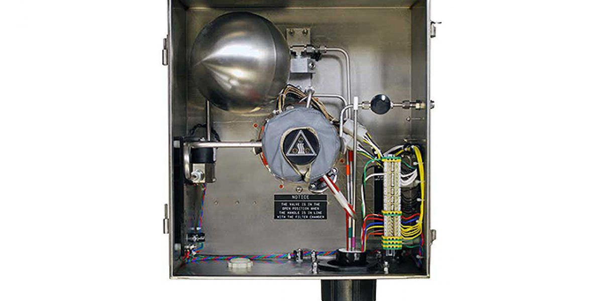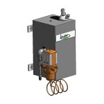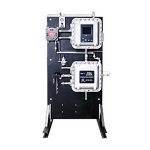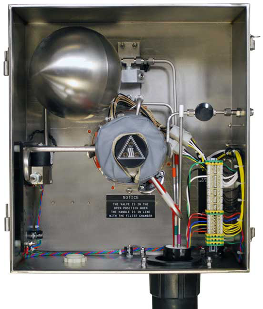
The Model 270F is a Flare Gas Probe Assembly consisting of the filter body mounted in a NEMA 4X stainless steel enclosure. A blowback system is provided to allow the blowback to occur on command from a data logger, PLC or UAI timer card or external switch mounted in a safe area.
Two 63 watt heaters are mounted in an aluminum sleeve around the filter cavity. The heaters hold the temperature of the filter near 270°F (132°C). A hermetically sealed bi-metallic thermal switch mounted to the filter body keeps the temperature from exceeding 280°F (138°C) by opening the circuit before that temperature. An optional independent temperature sensor can be provided as a means to measure and transmit or record the temperature of the filter. A second thermal switch, set at 225°F (107°C) is provided to be used as an alarm contact if the temperature drops below the switch temperature. An isolation valve is included in the sample path leading to the heated chamber. This valve is provided to protect maintenance personnel. It isolates the chamber from the process flare gas during filter changes. This valve is also heated with two 63 watt heaters, controlled to 270°F (132°C) and alarmed at 225°F (107°C) in the same manner as the heated filter. A second valve, heated and alarmed in the same manner, can be provided for further protection to personnel. A bleed port from between the first and second isolation valves will also be provided to allow releasing any trapped gases between these valves to avoid pressure build up due to valve leakage or temperature changes.
In colder climates an additional heater can be supplied for the enclosure. This heater will maintain 194°F (90°C) inside the enclosure.
The Model 270F Flare Gas Probe is provided with a 2 μm ceramic filter. This filter is supplied as an economical general purpose filter. It also has the advantage of being relatively non-reactive to the sulfur content of the sample gas. Additional filtration materials and pore sizes are available.
Blowback air is used to clean the filter element. Compressed air supplied to the blowback assembly needs to be clean and dry (-40°F/°C recommended). Instrument quality air is preferred. The pressure should be as high as possible, up to 125 psig (8.6 barg). High pressure air fills the accumulator (a 7” (178mm) diameter stainless steel sphere) and provides a substantial blast when the high flow solenoid valve opens. This loosens the particles on the filter surface and forces them back through the sample probe into the sample point. The period between blowback cycles should be set to occur before the pressure drop across the filter begins to increase beyond acceptable limits. By installing and monitoring a vacuum gauge ahead of the sample pump, a maintenance interval can be established. This can be as often as every 15 minutes but should be no less frequently than once per day. The period between blowback cycles can be based on calculations to estimate the amount of sample required to deposit from three to five grams of solids in the filter element. 1/4” instrument air line. The recharge time could be extended with a restriction in the air line if it were desired to reduce the pressure pulses on the instrument air supply and to consume instrument air even more slowly.
The calibration gas may be injected into the chamber ahead of the filter. This is close to the sample source, as is required by many EPA officers. A back pressure check valve (set at 3 psig (0.2 barg)) is provided in the cal gas injection path to insure that calibration gas does not leak into the sample while the sample is being drawn through the filter. Alternately, a three-way valve may be supplied to switch between calibration gas or sample gas, providing for a closed loop calibration with no calibration gas lost to the flare line.
System seal between the enclosure and process is provided by a sub flange mounted on the main flange. The probe tube and filter chambers are mounted on a separate sub flange. The primary sub flange mounts the isolation valves and filter chamber on one side, and the probe tube on the other. The remainder of the system seal between the enclosure and the process is maintained either by a triple O-Ring seal, or by a retractable probe tube support assembly.
For the triple O-Ring seal, the secondary sub flange is mounted directly onto the flange. This secondary sub flange seals the probe enclosure from process with a gasket between the sub flange and the main flange, and with a triple O-Ring seal on the probe tube. The primary sub flange may be removed from the flare probe assembly without disturbing the secondary sub flange. This allows the filter chamber assembly and probe tube to be extracted from the process and isolated from the process by means of a process side root valve, without ever losing system seal.
Because the probe tube is sealed by the triple O-Ring seal in the secondary sub flange, a specific style of probe tube is required. The probe tube will need to be specifically sized, and must be coated with SilcoNert™ to maintain a faster response time in samples containing sulfur. The probe tube must have a probe stop to prevent it from being ejected from the secondary sub flange and allowing process gas to escape.
The retractable probe tube support assembly has a secondary and a tertiary sub flange. The tertiary sub flange mounts to the main flange and seals the enclosure from the process with a gasket. The secondary sub flange has a probe tube support attached, and seals to both the probe tube and to the tertiary sub flange by means of O-Rings. The probe tube attaches to the primary sub flange, with its filter and isolation valves. The probe tube can be retracted into the probe tube support, and the probe tube support can then be retracted through the tertiary sub flange, all without losing system integrity.
The probe tube used with the retractable probe tube support is unique to this style of probe. The probe tube used with the triple O-Ring design cannot be used with a retractable probe tube support.
Features
- Environmental Purge with FM Approval for Hazardous area installations
- (C1, D2 grp’s a,b,c,d, T3A, ambient up to 93°C/199°F)
- NEMA 4X Stainless Steel weather protection enclosure with test port for H2S detection
- Heated filter chamber with 2μm, Ceramic filter element for particulate capture
- Filter Blow Back with integrated high volume air accumulator vessel and solenoid valve
- Retractable Probe tube with stop and proprietary triple o-ring seal for “hot tap” installations
- Custom probe tube lengths and diameters to meet velocity and stack/pipe diameters
- Chemical resistant O-rings/Seals and all wetted metal components Silconert™2000 treated
- Optional Process Isolation / Double Block / Block & Bleed valves w/manual or pneumatic actuation
- Enclosure includes sample line heat shrink boot with options for all pneumatic and electrical connections internal or through bulkhead fittings and a junction box on the side of the enclosure
- Cold weather options are available with full enclosure insulation and freeze protect heat
Applications:
The Model 270F is designed to meet “EPA 40 CFR 60 subpart ja” as well as “SCAQMA rule 1118” for flare related emissions at Refineries, Hydrogen Plants and Sulfur Recovery Plants.
Flare Stack monitoring comes with several challenges that require measures be taken for personnel safety, high velocity measurements and NEC NFPA compliance.
The UAI model 270F specific gas sample probe and the O’Brien TrueTube™ EPS heated sample transport line provide the best technical solution for point of measurement safety and fast response time to the analyzer requirement!
Operating Specifications
| Sample Flow Rate: | 0 to 20 l/m |
| Calibration Gas Requirement: | Sample flow rate plus 10% |
| Operating Pressure Drop at 10 l/m: | 12” water column (0.03 bar) |
| Maximum Stack Temperature: | 700°F (370°C) |
| Oven Temperature: | 270°F (132°C) |
| Enclosure Dimensions: | 19” H x 17” W x 17” D (480mm H x 430mm H x 430mm D) |
| Weight: | 108 lbs (49 kg) (plus probe) |
| Input Voltage Requirement: | 115VAC 50/60 Hz / 230VAC 50/60 Hz |
| Input Power Requirement: | 575 watt maximum (External Fuse Required of 20 A or Less) |
| Ambient Temperature, Operating: | 176°F maximum (80°C) |
| Blowback Tank Volume: | .01 scf (2.8l) |
| Blowback Duration: | 1.5 sec to empty accumulator |
| Enclosure: | SS, IP 65 |
| Sample Line Connection: | 3” Heat shrink boot (standard) 4” Heat shrink boot (optional) |
| Heater Type | Rod heaters in aluminum block, controlled with thermal switch |
| Available Filter: | 2 μm ceramic |
| Chamber Material: | 316SS, SilcoNert™ coated |
| Hazardous Area Classification: | Class I, Div. 2, Groups B, C, D |

