| Flow Capacity L/min | |||
| Ambient Temp. (°F) | 77° | 90° | 105° |
| 12% H20 Vol. | 5 l/m | 4 l/m | 3 l/m |
| 15% H20 Vol. | 4 l/m | 3 l/m | 2.5 l/m |
| 30% H20 Vol. | 2 l/m | 1.8 l/m | 1.3 l/m |
| 50% H20 Vol. | 1 l/m | 0.9 l/m | 0.7 l/m |
| Air Requirement SCFM | 4 | 4 | 4 |
| Exit Dew Point (°C) | 4 | 4 | 4 |
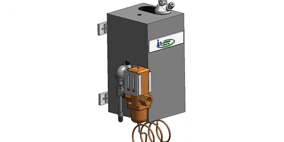
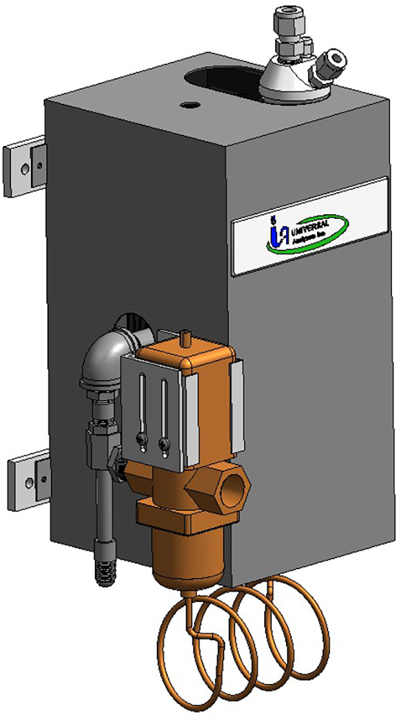
The 1100 series vortex sample gas cooler chills the sample through the use of a Vortex Tube. Clean dry compressed air, preferably Instrument Air, supplied by the plant passes through a “generator” within the vortex tube which separates the high velocity molecules from the low velocity molecules to provide cold air within the sample cooler which removes heat from the sample. Three square feet of heat transfer surface, inside the cooler transmits the heat from the gas sample.
The key to the success of the Universal Analyzers Sample Cooler being able to condense the water from a wet gas sample with a minimal loss of the water soluble gas fraction is due to the design of the heat exchanger. The separation occurs in a classical impinger which has a highly polished cylindrical surface cooled to the desired dew point temperature. The gas sample is brought to the bottom of the cylinder through an insulated tube and allowed to rise through a narrow annular area to insure the entire sample is influenced by the cold surface. The condensate flows down the cold polished surface in the form of a sheet (as opposed to droplets or the bubbling of the gas sample through the condensate) which minimizes the surface area in contact with the gas sample.
The internal, three square ft. heat sink is machined into fins from pure aluminum. (These fins are then anodized to better transfer heat to the cold air which is directed at the heat sink by the vortex tube.) The pure aluminum material is a far better conductor of heat than the aluminum alloys which are normally used for extruded heat sinks. The result is an assembly which has superior heat exhausting capabilities.
A thermal valve is supplied as a control valve to limit the air supply approaches freezing. The thermal valve is operated by a thermal bulb located within the heat transfer block and connected with a capillary tube. This control valve is a non-electric valve (actuated by the captive fluid within the thermal bulb). Since it is non-electric, is suitable for use in Division 1 or 2 hazardous areas.

