Process Oxygen Analyzer (2’nd Gen) for Industrial Process
Control & Monitoring of trace O2, %O2 and Dissolved Oxygen
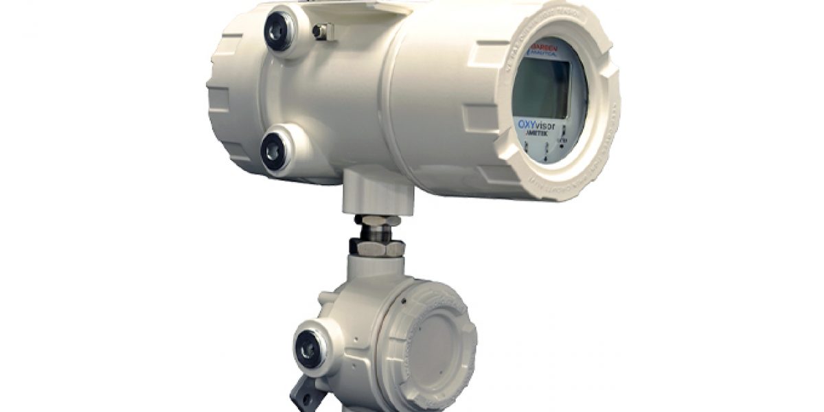
OXYvisor Introduction
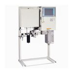
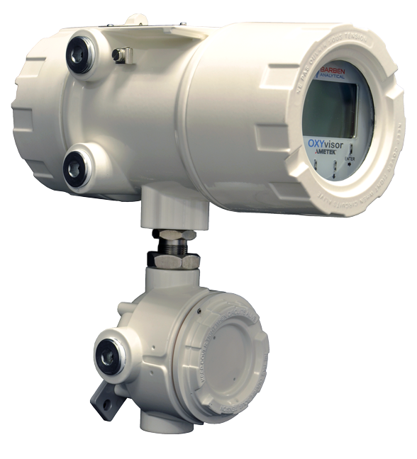
The OXYvisor is a process oxygen analyzer, best utilized to measure oxygen concentration in continuous, online, process monitoring and control applications. It is commonly referred to, as a O2 analyser, oxygen meter, dissolved oxygen meter or DO meter. The device utilizes an optical quench luminescent technique to measure oxygen concentration by volume (ppmv, molar basis) in gas phase or dissolved oxygen measurement (ppbv, ppmv) in liquid and aqueous phase applications. The oxygen meter is coupled, via a flexible fiber optic cable, of optional lengths, to a small external oxygen sensor that can be placed into an extracted sample stream, or directly in-situ to the process stream as a gaseous oxygen sensor or when used in liquids as a dissolved oxygen probe dissolved probe or optical DO sensor.
The OXYvisor is intended to measure oxygen concentration, in a wide array of industries and applications. Extensive North American (NEC/CEC) and international (IEC Ex/ATEX) hazardous locations and safety certifications, along with its robust industrial design, allow for use indoors, outdoors and within laboratories. The analyzer is used in the Oil & Gas (upstream/midstream, offshore, refining & petrochemical) hydrocarbon industry along with manufacturing (annealing furnaces, fiber optic production, contact lenses, etc.) and Renewable Energy Production (bio-gas & ethanol) markets. Common applications for upstream and midstream, are trace O2 (ppm) in VRU’s, Gathering Lines, Booster/Compression Stations, Gas Plant Inlets and Custody Transfer points along with CO2 lift and floodwater for Enhanced Oil Recoveries (EOR). Whereas common applications for downstream include nitrogen headers, tank blanketing, anaerobic digesters and Mercaptan oxidation (MEROX).
OXYvisor’s optical technique is an ideal technology for many of these applications, due to its ability to accurately measure in applications with high moisture or contaminants like H2S, CO2 and H2 with high reliability. It has no electrolyte to poison, no membrane to plug or foul, and is good to operate with high moisture and in liquids. This makes the OXYvisor an ideal upgrade for older technologies, such as para-magnetic analyzers, electrochemical cells ( e.g. fuel cells, galvanic dissolved oxygen sensors, amperometric probes & amperometeric gas sensors) and even in some cases, zirconia and TDL based technologies.
Capabilities & Features Overview
- Measures the oxygen concentration or process or sample in either
- Gas phase – capable range of trace ppm, 0.5 ppm, to percent level oxygen
- Liquid phase – capable range of trace, 1 ppb, to high ppm level dissolved oxygen (D.O.)
- Oxygen concentration measurement and calibration is temperature and pressure compensated
- Temperature Input: Pt1000 RTD
- Pressure Input: Standard on-board ambient pressure sensor or external 4-20 mA loop powered input
- Measurement accuracy, drift, and lifetime not affected by %H2S, CO2, SO2 and H2
- Standard calibration uses two-point, zero & span calibration gases
- Standard unit capable of Auto-Calibration and Remote Validation
- Rugged IP66, NEMA 4x enclosure with ambient operation -20 to 55 C
- Hazardous area approvals
- Zone 1 & Zone 2 (IEC/ATEX/CEC/NEC)
- Class I, Div 2 – (cULus)
- OXYvisor PC software for configuration, set-up, diagnostic and trending
- USB data trend storage (.csv file)
- Works with all BOSx oxygen sensors
- FiberSense (original), a small 4mm optical fiber integral O2 sensor for use in 1/4” tube fittings
- FlexSense I & II (inline flowcell) with simple replaceable BOSx sensor caps
- SafeTap Insitu (insertion/retraction), with simple replaceable BOSx sensor caps
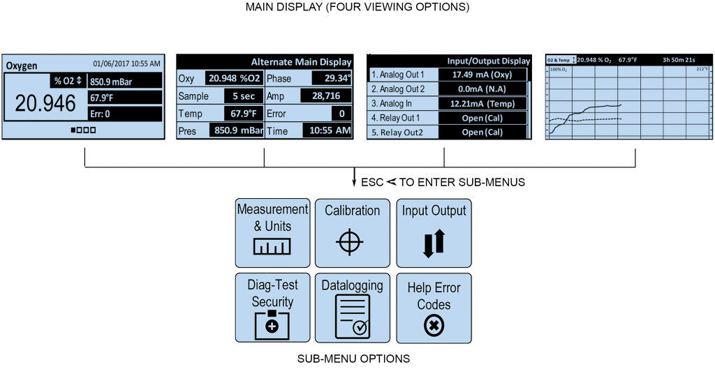
- Local display HMI, with through-the-glass operation allows setup and configuration
For more information on Barben Analytical’s BOS Oxygen Sensors and our sample conditioning panel products please refer to the separate data sheets for these products:
Barben Optical Sensor (BOS) – Data Sheet
Sample Calibration Panel – Data Sheet
Typical Applications – Gas Phase (g) – Process Oxygen Analyzer
- O2 in hydrocarbon streams
- Gathering Lines, Booster nad
- Vapor Recovery Units (VRU’s)
- Biogas
- Custody Transfer/Metering Stations
- O2 detection in nitrogen headers
- O2 in process streams
- Ethylene
- Propylene
- O2 in nitrogen tank blanketing
- Trace level oxygen in flare gas
- Limit of Detection: 0.5 ppm O2 @ 1atm, 20ºC (0.0005 hPa)
Typical Applications – Liquid Phase (l)
- High pressure produced water Dissolved O2
- ppb dissolved O2 for waterflood injection
- Oxygen in methanol and ethanol
- Oxygen in oils
- Dissolved O2 in liquid process streams
- Dissolved O2 in product streams
- Limit of Detection: 1 ppb Dissolved O2
Principle of Operation
The OXYvisor analyzer uses an optical phase fluorometric technology to measure process oxygen. Phase modulation of the luminescent decay time of an oxygen specific luminophore allows the calculation of the partial pressure of oxygen concentration with the process stream.
The analyzer uses an LED to emit blue light through fiber optic cable down to the luminophore which resides at the sensor tip [Fig 1]. The luminophore absorbs the energy and rises to an excited state indicated by red light returned through the fiber optic cable. The properties of the emitted light are measured through a photomultiplier tube back at the spectrometer within the analyzer.
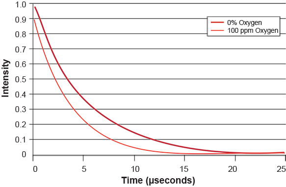
In the absence of oxygen, the excited luminophore will fall back to its ground state at a specific intensity and phase angle. When oxygen is present it quenches the fluorescence at a lower rate proportional to the oxygen concentration [Fig 2.]. The phase shift and intensity differences between the excitation source and the fluorescent signal is measured and the oxygen concentration is calculated [Fig 3].
The resulting measurement is specific to oxygen concentration. The luminophore is unaffected by other contaminant gases and flow rate. The measurement is applicable in both gas and liquid phase. Temperature compensation is required to account for quenching efficiency at different temperatures and pressure compensation is required to measure at process pressured different from the pressure at time of calibration.
| Figure 1 |
 |
| Figure 2 |
 |
| Figure 3 |
 |

